

Starpower: Automation power modules - typical failure modes and how to solve them
IGBT failure analysis – first aid for emergencies
Power modules are considered critical components that usually undergo a rigorous testing cycle in the design phase of the application. Field failures then often come as an unpleasant surprise and failure analysis is rarely straightforward but more often a detective game.
Failure description and analysis
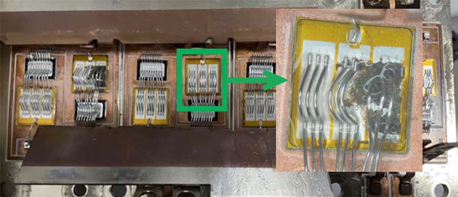
Figure 1: Image of failed IGBT-die with molten top metallization
Opening up a failed IGBT-module often reveals one or several dies with black spots, which, under higher magnification are visible as molten layers of the chip’s top side metallization. Generally, this is caused by either by current or voltage spikes, an explanation however too general to derive any further actions of how to prevent it from repeating. Naturally, the finger of blame is often pointed at the manufacturer and parts returned for further analysis.
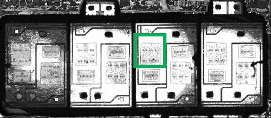
Figure 2: Ultrasound analysis of solder connection between die and DBC
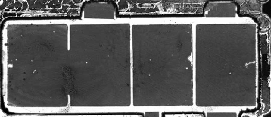
Figure 3: Ultrasound analysis of solder connection between DBC and baseplate
On return and after visual inspection, the manufacturer would usually attempt to measure the static and dynamic electrical parameters and compare them with the specified values in the data sheet. Often however, the dies are degraded to an extend that this process yields either no or mostly inconclusive results. The next logical step is to check for manufacturing errors, especially by analysing the solder layers as voids here often directly lead to either bond lift-offs or in severe cases complete melting of the chip metallization. In this particular case however, Fig. 2 and 3 show no abnormalities in the solder connection. Looking at modern production lines of IGBT-modules operated by StarPower and other leading manufacturers, this result is not surprising. In-line x-ray testing combined with automated optical inspection (AOI) finds and sorts out modules with out-of-spec solder connections before they can reach the customer. Scheduled sheer tests verify the bond connection and every module is 100% tested on static and dynamic electrical parameters as well as isolation before it leaves the production line.
Finding the root cause
Not uncommonly, the conclusion after 8D-analysis of failed modules in the field is that they worked within specification before leaving the factory of the module supplier, potentially even at assembly of the application but then failed in the field at some point after. Failures occurring only occasionally can be especially hard to identify often with no quick fix. Looking at failures over the life of the application, one often thinks about end-of-life wear-out failures after a significant time of operation. To offer predictability and reliability in this part of the bath-tub curve (Fig. 4), module manufacturers perform process qualifications in the design phase of the module. These tests include mechanical stress, high temperature and humidity as well as power and thermal cycling assessments – often referred to as accelerated ageing. The main purpose here is for the manufacturer to adjust its processes to meet the customer’s reliability expectations towards the end of the product life cycle and help to identify the time when this end is likely to occur.
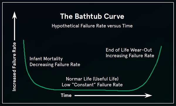
Figure 4: Bathtub life cycle curve for technical applications ©www.weibull.com
It can happen that returned modules have failed right at the beginning of the application life cycle in the early stages of the bath-tub curve. Finding root-causes and potential fixes here is not easy and therefore, a systematic approach is recommended that should include the following considerations.
Step by step approach
From optical inspection, it is often straightforward to identify whether the IGBT and/ or the diode chip has failed. The following diagrams provide a non-exhaustive checklist of potential failure mechanisms that can be traced back mainly to the driver and protective circuit of the application and provide ideas of where to look for modifications on the respective PCB.
Looking at the IGBT, the first area to consider is the Reverse Bias Safe Operation Area (RBSOA) illustrated in Fig. 5, which is usually described as a range of Vce and Ic under which the module can be operated without concern. The corresponding graph is typically described in the module data sheet.
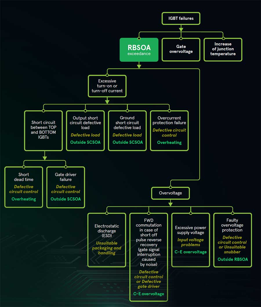
Figure 5: IGBT failures caused by RBSOA exceedance
Fig. 6 illustrates failure mechanisms linked to a sudden increase in Tj leading to delamination of the chip layers and in worst case melting of the top metallization.
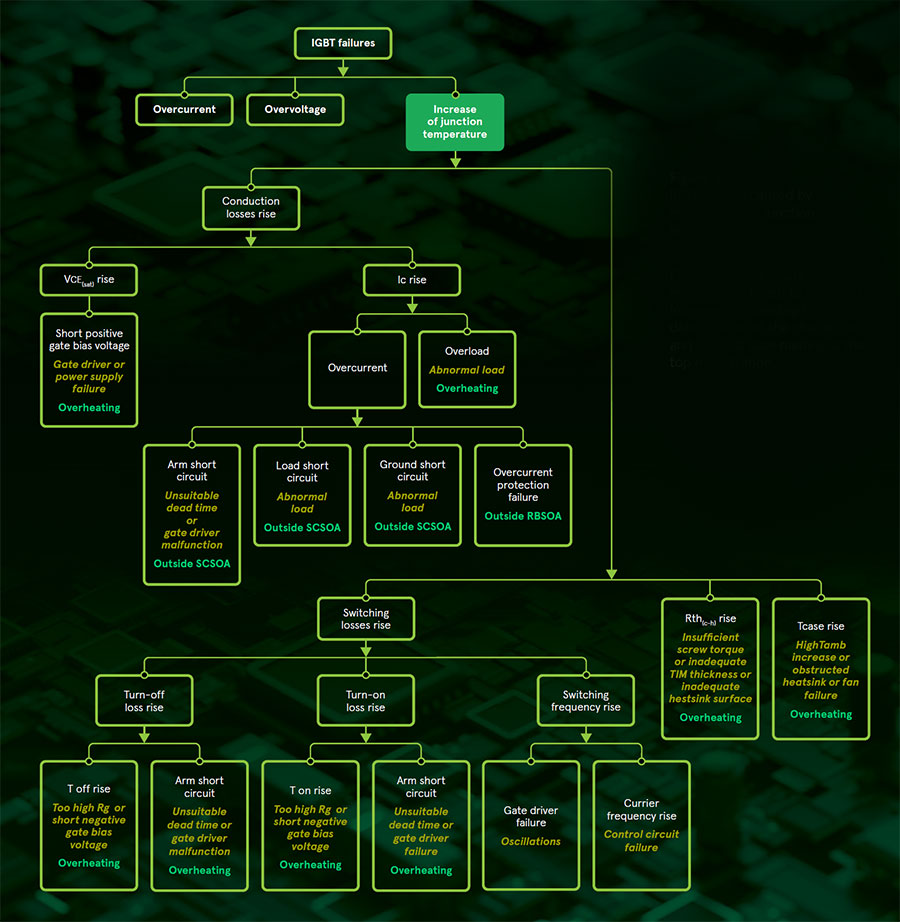
Figure 6: Failures caused by exceedence of junction temperature
The other main area to consider in the IGBT-module is the FWD diode chip, which is deployed as a standard together with every IGBT die. Fig. 7 highlights again overvoltage events as a main source of these events, caused often by defective or unsuitable gate driver or control circuitry.

Figure 7: Failures caused by overvoltage at the free-wheeling diode

Figure 8: Failures caused by overvoltage at the free-wheeling diode (FWD)
Sudden increase in Tj on the FWD can be a final area to look at as highlighted in Fig. 8.
Conclusion
Optical inspection of failed IGBT modules often show the effects but rarely give indication of the deeper cause of failure. Standard analysis techniques performed by the manufacturer can verify potential errors within the production process and help to find preventive solutions quickly and effectively. However, due to modern process control and inspection within the automated production lines as well as qualification tests in the module design phase, the result of such analysis often shows that no root cause can be attributed to the manufacturer directly. This leaves customers with a complex and often frustrating search within the application for which we want to provide guidance as well as assistance by our experienced FAE team.
Click here to learn more about Starpower IGBT modules for motor driver application.


