

Power solutions to meet space constrained applications
Power density requirements and increased focus on protection features make digital power modules a great option in space constrained applications
High performance computing, storage, networking equipment, industrial and automated test equipment are migrating to digital power modules due to space constraints and demands for higher currents. The currents levels required by custom ASICs, FPGAs, DSPs and memory continue to increase due to increased functionality required in these applications. Designers are also expecting more protection features from their power delivery network to insure a robust system level design. This article highlights the benefits of using a digital power module in your next design.
While power modules are not new to the industry, its use is getting more widespread as systems strive to decrease in volume and footprint. As a result, board space allocated to power circuitry diminish as systems strive for greater integration. Figure 1 shows an illustration of moving from discrete power supply to power module implementation.
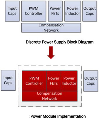
Figure 1. From discrete power supply to power module implementation.
Some application areas of power modules include circuitry of high complexity, stringent space limitations and high current designs where power density is of utmost importance. By integrating the various components of a power supply design into a single compact product, a simple, easy to use solution can be very attractive and helpful in such applications. Besides a small compact design, there is a shift in preference towards PMBus enabled products, where output voltage, switching frequency, loop compensation parameters can be easily changed through the GUI.
In addition, the product should also contain the various protection features that protects itself as well as the circuitry downstream. Some of the protection features include overvoltage and undervoltage protection, positive and negative overcurrent protection and over temperature protection. All these should also be easily accessible to be modified by the user in the GUI through PMBus.
As an example, the RAA210130 as a fully PMBus enabled 4.5V-to-15V DC-DC step-down power module is capable of delivering up to 30A of current from a compact 10mmx13mmx7.8mm thermally enhanced BGA package. The module comprises of a full digital controller, a Smart Power Stage (SPS) with both top and bottom MOSFET, internal power supplies to power the controller and SPS, and a filter inductor, making this module a robust and self sufficient power supply.
The module implements the proprietary Renesas digital synthetic current modulation scheme to achieve excellent transient response, ease of tuning and efficiency across the full load range. This achieves a smaller total output voltage variation with less output capacitance than traditional PWM controllers. With minimal external components, simple configuration, robust fault management, and highly accurate regulation capability, implementing a high-performance regulator has never been easier.
A standard PMBus interface with PMBus V1.3 compatibility facilitates device configuration, addresses sequencing and fault management, provides real time full telemetry and point-of-load monitoring, and detailed fault reporting. All of these features are conveniently accessible through the PowerNavigator™ software tool. A fully customizable cycle-by-cycle current, voltage and temperature protection scheme is capable of latching off or restarting the output in response to system faults.
Figure 2 shows the comparison between (a) discrete solution and (b) power module implementation.
(a)

(b)

Figure 2. Comparison between (a) discrete solution and (b) power module implementation
1. Performance
The RAA210130 offers excellent efficiency over the entire load range. Figure 3 show the efficiency vs. load current at VIN = 12V, with (a) internal and (b) external 5V and 3.3V supply where the peak efficiency is 95.5%. Besides excellent efficiency, RAA210130 also provides impressive transient response. Figure 4 shows the outstanding transient response at VIN=12V, VOUT = 0.8V, with a step load of 30A, where the VOUT undershoot/overshoot of less than ±2.5% can be achieved. Figure 5 shows the transient response at VIN=12V, VOUT = 3.3V, with a step load of 15A, where the VOUT undershoot/overshoot of less than ±1% can be achieved.
(a)

(b)
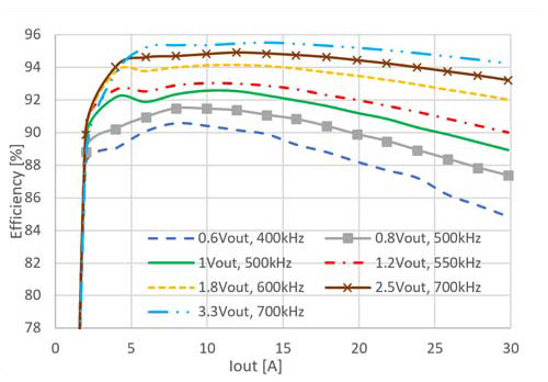
Figure 3. Efficiency vs Load Current at VIN = 12V, with (a) internal and (b) external 5V and 3.3V supply

Figure 4. Transient Response, VIN=12V, VOUT = 0.8V, 0-30-0A, 5A/us step load
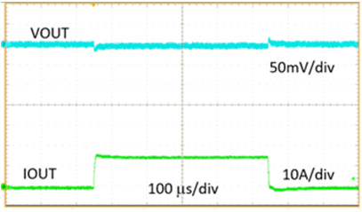
Figure 5. Transient Response, VIN=12V, VOUT = 3.3V, 0-15-0A, 5A/us step load
2.Protection features
The RAA210130 includes an extensive fault management system that integrates with high performance host controllers, supporting unprecedented remote system management and debugging capability. If a fault condition occurs, the controller de-asserts the PG pin and alerts the host using the nPMALERT pin. The Catastrophic Failure Protection (CFP) can be optionally configured to assert on select faults for additional protection measures at the system level. The RAA210130 also provides a Black Box, which is a recorder with extensive fault logging to support system level debug. Fault controls are independently enabled and associated fault responses are user configurable.
2.1 Power-Good signal
The PG pin is an open-drain, power-good output that indicates completion of the soft-start sequence and output voltage is within the expected regulation range. If a fault occurs or when the rail is disabled, the PG pin is pulled low.
2.2 Overvoltage/Undervoltage Protection
Output voltage is measured at the load sensing points differentially for regulation, and the same measurement is used for OVP and UVP. Figure 6 shows a simplified OVP/UVP block diagram. The output voltage comparisons are done in the digital domain.

Figure 6. OV/UV Comparators
The device responds to an output overvoltage or undervoltage condition by disabling the output, declaring a fault, setting the PMALERT pin, pulling the PG pin low, and then pulsing the LFET until the output voltage drops below the threshold. The output does not restart until the EN pin is cycled (unless the device is configured to retry).
The RAA210130 also features open-pin sensing protection to detect an open of the output voltage sensing circuit. If this condition is detected, module operation is suspended.
2.3 Output Overcurrent Protection
The RAA210130 offers a comprehensive overcurrent protection scheme that monitors the total output current, peak phase current, and the valley phase current. The scheme allows the user to eliminate inductor saturation and limit the total output current. Shutdown and retry response types for OC faults are supported. The response configuration applies to all output current fault mechanisms such as phase peak overcurrent and total output overcurrent.
Figure 7 shows the block diagram of the output overcurrent protection scheme.

Figure 7. OCP Functional Diagram.
The module is protected from both overcurrent and undercurrent using a pulse-by-pulse scheme that acts instantly on a PWM signal if a detected inductor current reaches its threshold. Thresholds for overcurrent and undercurrent (negative inductor current) allow the user to precisely limit the phase current to prevent inductor saturation. Current limiting behavior can be configured to either shut down the device after a user-determined number of consecutive events or continue indefinitely. If configured to continue indefinitely, the converter behaves much like a current source. Figure 8 and Figure 9 show the OC and UC current limiting when the device is configured to shut down after a finite number of consecutive events.

Figure 8. Peak OC Operation.

Figure 9. Peak UC Operation.
The RAA210130 also supports total output current limits that have user-adjustable response delay. The two sum current limits, fast and slow, allows the user to permit high maximum output current for a shorter period of time and lower output current for a longer period. The response delay for the limiting mechanisms is also adjustable. These mechanisms do not restrict the maximum output current until the current has exceeded a threshold for the response delay time. Figure 10 shows the total output current protection scheme.

Figure 10. Total Output Current Protection.
2.4 Thermal Protection and nVRHOT
The RAA210130 supports a comprehensive scheme for thermal alerting and protection. It monitors SPS temperature and supports over-temperature and under-temperature faults in addition to over-temperature warning. The controller temperature is monitored to support telemetry and thermal shutdown. Shutdown occurs at approximately +130°C. The nVRHOT pin is used at the system level to inform the powered device to reduce its power consumption. nVRHOT is an open-drain output; an external pull-up resistor is required. This signal is valid only after the controller is enabled. nVRHOT is pulled low when the sensed temperature reaches the PMBus OT_WARN threshold, providing the powered device with an advance warning of the controller thermal status.
Figure 11 shows the behavior of nVRHOT and an over-temperature fault shutdown.

Figure 11. nVRHOT and Over-Temperature Shutdown.
2.5 Catastrophic Failure Protection
The CFP pin supports Catastrophic Failure Protection (CFP) functionality. The pin can be configured to activate in the event of a catastrophic fault detection. The function is typically used to immediately disable the input supply to protect the entire system. The CFP function can be configured to respond to output overvoltage, input overvoltage, and/or output overcurrent faults.
2.6 Black Box Recorder
Black Box is a powerful diagnostic tool that captures all telemetry and status information when any fault occurs. The RAA210130 continuously monitors rail information along with the time duration for which the rail has been regulating, and the tool captures that data when a fault is registered. The tool reports the first fault bit that occurred to cause the shutdown. This diagnostic data is stored in RAM, and Black Box can be configured to additionally write to NVM for retrieval when the system loses input power and a fault occurs. The RAM record is updated every time a fault occurs. Black Box can write to NVM up to 10 times and provides an option to limit NVM writing to once per power cycle to avoid filling up the available NVM space inadvertently.
3. Conclusion
There is a growing trend in preference towards a small footprint, ease of use and fully PMBus enabled DC-DC step-down converter. Whilst being capable of achieving excellent transient response and maintain good efficiencies across the full load range, compatibility with the standard PMBus interface helps simplify device configuration, address sequencing, fault management and reporting, full telemetry and point-of-load monitoring. In terms of protection, it is necessary for the product to offer a fully customizable cycle-by-cycle current, voltage and temperature protection scheme. RAA210130 is an embodiment of all the above-mentioned features for your application needs.
Learn more about RAA210XXX Single Channel Digital Interface Power Modules: Click here


