How to use LabVIEW for FPGA Based Application
How to use LabVIEW for FPGA based application
You can use LabVIEW to program a FPGA through the LabVIEW FPGA add-on module and design FPGA-based systems more effectively and efficiently through a highly integrated development environment that has IP libraries, a high-fidelity simulator, and debugging features. It helps develop FPGA VIs that combine direct access to I/O with user-defined LabVIEW logic to define custom hardware for applications such as digital protocol communication, hardware-in-the-loop simulation, and rapid control prototyping. It contains many integrated signal processing routines. You can also incorporate existing hardware description language (HDL) code as well as third-party IP. Use this module to program various NI-specific hardware like CompactRIO Systems (cRIO), FlexRIO, PXI Multifunction Reconfigurable I/O Module, Industrial Controllers, etc. Figure 1 shows a general block diagram to program NI FPGA hardware using LabVIEW.

Figure 1: General block diagram to program FPGA
To illustrate, we will connect a cRIO-9076, an industrial embedded controller from NI, to control and monitor applications. It features a real-time processor and a Xilinx Spartan-6 LX 45 FPGA with Ethernet, USB, and serial connectivity ports. For input and output, we will use NI-9421, 8- channel digital input module, and NI-9474, 8-channel digital output module, which is used with the cRIO module. Each channel is compatible with 24 V logic levels and has an LED indicating the state of that channel.
The following steps create an FPGA application that accepts a digital input and generates two digital outputs toggling each other in high and low logic levels. The application is implemented on the host LabVIEW machine, compiled, and deployed on the cRIO-9076 FPGA machine.
Hardware Connections:
As shown in figure 2, hardware connections are made where the input and output module has been plugged into the cRIO chassis slot. A 24VDC power supply is connected to the DI0 channel of the input module in series with a toggle switch. The output module is powered through 24VDC, and output can be checked on the DO0 and DO1 channels of the output module. Connect host PC to cRIO chassis with a network cable (blue cable in the figure).

Figure 2: Hardware connection
To implement the LabVIEW program, we need to install LabVIEW, LabVIEW FPGA Module, LabVIEW Real-Time Module, and NI-RIO Driver on the windows based host PC.
LabVIEW Program:
Execute the following steps to write the LabVIEW program.
Open LabVIEW application and create LabVIEW FPGA project, which will detect connected hardware and open project window as shown below.
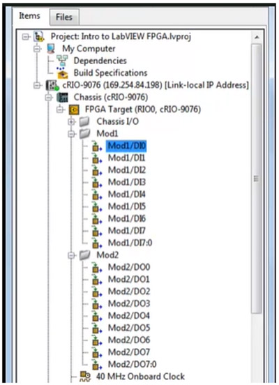
Figure 3: LabVIEW FPGA project window
This project window includes two categories: My Computer, which is to create an application on host pc, and c-RIO-9078 (169.254…) which is to make an application on target RT machine (cRIO-9076). Now navigate to cRIO-9076->Chassis (cRIO-9076)->FPGA Target (RIDO, cRIO-9076), do right-click, and create a new VI that will open the window as shown below figure. The code on this VI will run directly on the target machine.

Figure 4: Blank FPGA VI window
FPGA target has built-in sub-VI to access its input and output channels like Mod1 and Mod2. Navigate to cRIO-9076->Chassis (cRIO-9076)–Mod1 and cRIO-9076->Chassis (cRIO-9076)–Mod2 and drag sub-VI Mod1/DI0, Mod2/DO0 and Mod2/DO0 on the block diagram and connect as shown in figure 5. Enclose the code in a while-loop, and to continuously run it, connect the control to FALSE (F) Boolean Constant. The code shows that when we input DI0 at high logic (24V), the DO0 will be low and DO1 high. With the low input, it will be reversed.

Figure 5: Writing LabVIEW code
After completing the code, click on the “RUN” button, which opens a new window for compiling the code on the target machine. Select the “Connect to LabVIEW FPGA Compile Cloud Service” giving NI credential and click Ok.

Figure 6: Compiling code on target
After successfully compiling the code, it will open the status window (figure 7). After this message, the target is ready to execute the application having running code.

Figure 7: Status window after compilation
Now, giving the input signal through the toggle switch will show status as below the truth table.
| DI0 | DO0 | DO1 |
|---|---|---|
| High | High | Low |
| Low | Low | High |
High level = 24V
Low level = 0V


