

How to select a transformer for an isolated buck converter
Introduction
Selecting a transformer can be a pivotal process for designing isolated buck converters. This tutorial discusses how an isolated buck converter works, which parameter to focus on when choosing a transformer, how these parameters influence the choice of transformer, and how the transformer influences a circuit parameter.
How does an isolated buck converter work?
Just like a buck converter, Figure 1 shows an iso buck topology. By replacing the inductor in a buck circuit with a transformer, the result is an iso buck converter. The transformer secondary side has independent ground.
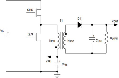
Figure 1. Iso-buck topology.
During on time, the high-side switch (QHS) is on, and the low-side switch (QLS) is off, the transformer magnetizing inductance (LPRI) is charged up. The arrow in the block diagram (Figure 2) shows the current flow direction. The transformer primary current increases linearly. The current ramping slope depends on (VIN - VPRI) and LPRI. The secondary-side diode (D1) is reverse-biased during this time interval and loads current flow from COUT to load.

Figure 2. On period equivalent circuit.
During off time (Figure 3), QHS is off and QLS is on and the transformer primary-side inductor is discharged. The primary current flows from QLS to ground, D1 is forward-biased, and the secondary current (NSEC) flows from the second-side coil to COUT and load. COUT is charged up during this time. (Turning off QHS and turning on QLS cannot change the current direction, it only changes the current slope. Positive current decreases until 0A, then the negative current increases).

Figure 2. Off period equivalent circuit.
Which spec will influence the transformer?
When designing a converter, some specs should be declared and defined as it will determine which component will be used, especially in a transformer.
- Input Voltage Range
- Output Voltage
- Max Duty Cycle
- Switch Frequency
- Output Voltage Ripple
- Output Current
- Output Power
Maximum duty cycle (D) is typically assigned in the range of 0.4 to 0.6. The minimum input voltage (VIN_MIN) and max duty cycle determine the primary output voltage (VPRI). The primary output voltage and output voltage (VOUT) determine the transformer turns ratio.
Output current (IOUT) and output power (POUT) are key parameters that influence transformer selection. Output current helps determine the thickness of the copper wire and output power determines which transformer skeleton is used. The permeability of the skeleton indicates how much energy it can store, and how much power it can put out. Generally, the DC output current multiplied by a coefficient is assigned to the inductor’s (transformer’s) ripple current. Duty cycle and switch frequency are used to calculate the TON time, while VIN, VPRI, and ripple current decide the primary inductance. The assigned coefficient must not be too large or too small since a large coefficient can lead to a large ripple current. Large ripple current may result in half the H-bridge current limit, which may damage the MOSFET. A large ripple current will lead to a large ripple voltage on the output capacitor due to its ESR and ESL. On the contrary, when an extremely small ripple current is needed, use a large inductance inductor (transformer). It will be a big skeleton with a large size of the transformer winding. The large inductance will limit loop bandwidth and the loop response performance.
Choosing a transformer
Obviously, energy was transferred to the secondary only in TOFF time. The turns ratio can be decided by the following equation:

Equation 1
Where VD is the diode (D1) forward-bias voltage. For Vpri, assign a maximum duty cycle in the range of 0.4 to 0.6. The Vpri can be calculated by the following equation:

Equation 2
Where D is the maximum duty cycle and VIN_MIN is the minimum input voltage. From Equation 2, calculate the turns ratio. Since the inductor is following volt-second balance low, the required inductance is calculated by the following equation in TON time:

Equation 3
Where f is the switching frequency and ΔI is the ripple current. As discussed before, ripple current equals the DC output current multiplied by a coefficient:

Equation 4
Where K is the coefficient. But in iso buck converter topology, there is a transformer not an inductor. How do we deal with this? The current ratio equals the turns ratio inversely:

Equation 5
Where Ipritoff is the secondary current, which is converted and transferred to the primary side during TOFF time. The sum of the primary and secondary-side current can be considered as an equivalent inductor current.

Equation 6
Where ILeq is the equivalent inductor current. If the transformer has three more windings, this is the following equation:

Equation 7
But is this correct? Let’s verify it with the simulation result based on the MAX17682. Figure 4 shows a screenshot of the MAX17682 typical circuit drawn in SIMPLIS. Current probes, IPRI and ISEC1, were placed on both sides of the transformer T1.
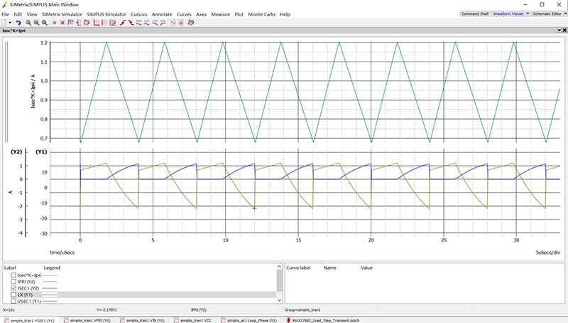
Figure. 4 MAX17682 typical circuit in SIMPLIS
Figure 5 is a screenshot of the transient simulation resulting from two probes. Two current waveforms were added by using the above equations.
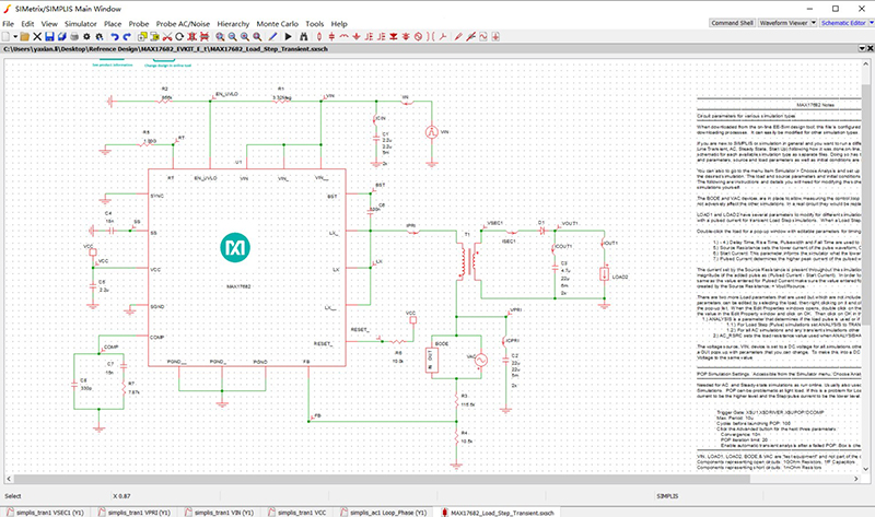
Figure. 5 Simulated current waveform of the MAX17682 typical circuit.
Clearly, the added current (cyan) results in a triangle wave, just as the inductor in a non-iso buck converter. The transformer primary ΔI can then be easily calculated:

Equation 8
Typically, an assigned load current ripple is 0.2 times the DC output current. K can be assigned to 0.2 times Nsec/Npri. At the same time, the primary peak current should be guaranteed less than the limited switch. Where Ipk is:

Equation 9
The transformer primary inductance can be easily calculated as:

Equation 10
By using the turns ratio, primary inductance, output power, output current, and isolation voltage parameters, a decision can be made on the inductor design.
Why Does the Simplified Equation Work?
There may be some uncertainty using the MAX17682 data sheet (Figure 6) when selecting inductance. t Let’s see how we can better understand it and use it for our application.

MAX17682 datasheet equation.
According to the above example, Equation 10 can be rewritten to follow this equation for TOFF time.

Equation 11
Assume D is 0.6, if and only if ΔI were 0.4A, the polynomial (1-D) and ΔI is reduced. Then Equation 11 and the equation from Figure 6 are the same. The equation in the datasheet already selects the primary ripple current. If we assign D as 0.6, the primary ripple current is 0.4A. In quantity, the TOFF duty cycle equals the primary ripple current.
Conclusion
By using the simplified equation shown in Figure 6, the user ensures a faster design with a primary ripple current that equals the Toff duty cycle. If you want to modify primary ripple current or use another parameter, this tutorial discussed how to implement that.
To learn more about MAX17682 Iso-Buck DC-DC converters Click here


