How to design multi-rail power supply unit using PMIC
A typical processing system in an electronic circuit has distinct multi DC power rails to support the core, MPU, analog units, external IO, DDR, eMMC, and the wireless network. A high-performance IC such as an FPGA can easily have half a dozen or more distinct DC power rails to support the device core, RAM, internal buffers, and external I/O such as I2C, SPI, LVDS, and other ports.
These rails may have different, but closely spaced nominal values, or several of these rails may have the same nominal value but different tolerances or physical locations (Figure 1).
PMIC, namely a Power Management Integrated Circuit, is the quickest way to build an efficient multi-rail power system for today's application systems, as it combines all the power control functions into a single chip. PMIC solutions can range from two simple power rails, to more than twenty with load switching for ADC, battery chargers, LED drivers, and other combinations.

Figure 1: Multi-rail power supply example for a processor and FPGA
A conventional option for creating the power tree in an electronic circuit is to use an individual power regulator integrated circuit (IC) for each rail. This is commonly referred to as a discrete solution. Figure 2a shows a processor that needs two DC-DC converters plus two LDO regulators and requires additional space around these components. The other option is to use a multi-rail PMIC (Figure 2b) with mostly integrated components. Using a single PMIC in place of many external components can help reduce board space and make schematic design and layout simpler.

Figure 2a: Discrete Processor Power (left) Figure 2b: PMIC Processor Power (right)
Design considerations
You should care about critical voltage regulation, high efficiency over wide load, small occupied space, and optimised PCB layout for each power rail. Consider the below sequence whilst designing a multi-rail PMIC based power supply unit.
1. First, determine your system requirements
This typically includes input voltage, output voltage, output current, size, and package. A well-regulated power supply with an optimised transient response is critical for subsystems and processors, for proper operation and reliability. Too high a voltage will cause permanent processor damage, and too low a voltage will cause the system to go into a brownout or UVIO condition, resulting in lost or corrupt data.
2. Next, select the right type of PMIC
There are mainly four different types of PMICs available in the market-- hardware configurable, software configurable, factory programmed, and user-programmable. Hardware configurable PMICs are similar to discrete devices but with multiple rails integrated into a single chip. Software configurable PMICs are controlled by an MCU rather than using external passive components. True to their name, factory-programmed PMICs are just that, pre-programmed in a factory before shipment. Finally, user-programmable PMICs are flexible and can be programmed to meet the needs of any processor.
3. Keep the board space in mind
A multi-rail PMIC usually integrates several power sources: buck converters, boost converters, linear dropout regulators (LDOs), reference voltages, clocks, and general-purpose inputs/outputs (GPIOs). Each power source can require components such as FETs, capacitors, inductors, and resistors. It is very important to start considering the placement of components and design to route power on PCBs.
4. Monitor or set up power sequencing
In most designs, multiple rails turn-on/turn-off sequences must be done in a specific defined order. Improper power sequencing can cause reliability problems, such as characteristics degradation, inrush current, and latch-up. To fully manage turn-on and turn-off sequencing, user-programmable PMICs have flexible options, along with fully programmable ICs that are designed specifically for sequencing.
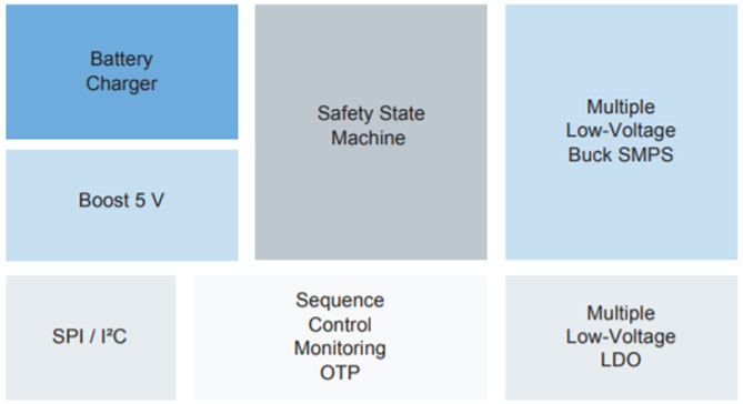
Figure 3a: A typical PMIC Block Diagram
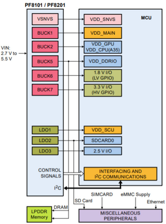
Figure 3b: PF8101/PF8201 PMIC from NXP designed for high performance i.MX 8 based applications, features five high-efficiency buck converters and three linear regulators for powering the processor, memory, and miscellaneous peripherals.
PMICs bring an advanced level of configurability and programmability at the system level for multi-rail power systems. System-specific function requirements vary as per the application, and the designer has the flexibility to choose accordingly. Additionally, battery management, system monitoring, fault handling, RTC, and interface management result in more efficient use of space and power.
Using a PMIC to power multi-rail systems enables flexible, simpler, efficient, and smaller designs. PMICs can power subsystems, the main processor, or the main processor and subsystem. Next time you have multiple power rails on your application, think about a PMIC.


