

IO-Link®, a Pivotal technology for smart Industrial Automation
Introduction to IO-Link
Historically, an industrial sensor included a sensing element and a way to transfer sensing data to a controller. Data was often transferred in analog format and was unidirectional (sensor to host/controller only). Unfortunately, this approach often added extra steps (e.g. digital-to-analog and analog-to-digital conversion) to the overall sensor functionality which, in turn, added extra cost, larger footprints and susceptibility to noise.
These “old school” sensors did work (and do continue to work today!), and as technology advanced, sensor manufacturers were able to integrate more functionality into sensors that eliminated some of these problems. Data, however, was still restricted to unidirectional communication from the sensor to the controller, limiting error control and often requiring manual calibration or updates. Manufacturers needed a better solution to meet the increasing demands for smart automated sensors and the solution that emerged was IO-Link. Analog Devices (ADI) provides a portfolio of advanced industrial automation solutions that create pathways toward achieving Industry 4.0, enhanced by its IO-Link technology portfolio.
IO-Link is a standardized technology (IEC 61131-9) regulating how sensors and actuators in industrial systems interact with a controller, allowing bidirectional communication and configuration between a sensor and a controller. IO-Link functionality in a system reduces maintenance, increases uptime, and transforms a manual sensor installation into one which allows a user to "plug-and-play and walk away." This type of communication between an IO-Link master and an IO-Link device allows for continuous diagnostics and improved data logging and error detection to further reduce operating costs. Commonly used connectors (for example M8 and M12) and cables, as explained in the IEC 61131-9, enable standardized installation with direct binary sensor upgrades.
IO-Link is very powerful and flexible, allowing some of the overall system intelligence to be moved closer to the sensors on the factory floor. An IO-Link master is coupled with a device using a standard sensor/actuator cable measuring up to 20 meters in length. The device - which may be any sensor, any actuator, or a combination of the two - transmits and receives data (binary switching, analog, input, output) that is transmitted directly via IO-Link in a digital format. Figure 1 shows a typical industrial sensor ecosystem including analog I/O, digital I/O, and IO-Link connection.

Figure 1: Industrial sensor ecosystem
As shown in Figure 1, IO-Link transceivers that include an additional digital output (DO) and/or digital input (DI) allow the device microcontroller to process binary signals in addition to IO-Link communication. For example, the additional DI and DO connections can allow the on-board microcontroller to also input signals from a binary sensor, and drive a lamp (e.g. if a threshold has been surpassed). In short, all processing can be done at the sensor itself.
Since IO-Link and binary sensors can have configurable settings (for example PNP, NPN, or push-pull outputs that can be changed while in progress), the number of product units the sensor vendor needs to support is also reduced. IO-Link communication allows parameter settings to be downloaded from the controller to set up, or reconfigure, a device. This means a technician is no longer needed to do initial setup and machine downtime is reduced when it is required to reconfigure devices.
IO-Link system
IO-Link is a standard for Single-Drop Communication Interface (SDCI) while also providing backwards-compatibility with binary sensors IEC 60974-5-2.
The connection between the IO-Link master (multi-port controller or gateway) and the IO-Link device (sensor or actuator) uses standard connectors and a 3- or 4-wire cable up to 20 meters in length. The master can have multiple ports (commonly four or eight). Each port connects to a unique IO-Link device, which can operate in either SIO mode or bidirectional communication mode. IO-Link masters can interface with both binary and IO-Link sensors, allowing IO-Link to be easily added to an existing system. IO-Link is designed to work with existing industrial architectures such as fieldbus or industrial Ethernet and connects to existing PLCs or human-machine interfaces (HMIs), enabling rapid adoption of this technology.
IO-Link communication is point-to-point between an IO-Link master and a device using a 3-wire interface (L+, C/Q, and L-). The supply range in an IO-Link system is 20V to 30V for the master, and 18V to 30V for the device.
The two communication modes between an IO-Link master and a device are standard I/O (SIO) and SDCI (IO-Link). In SIO mode, backward compatibility is ensured with existing sensors in the field, using 0V or 24V to signal OFF or ON to the IO-Link master. In IO-Link mode, communication is bidirectional at one of the three allowed data rates: COM1 (4800 baud), COM2 (38.4kbau), and COM3 (230kbaud). The IO-Link device only supports one data rate while the IO-Link master must support all three data rates. Communication typically uses 24V pulses using a nonreturn-to-zero (NRZ) on the C/Q line where a logic 0 is 24V between C/Q and L- and a logic 1 is 0V between C/Q and L-. In IO-Link mode, pin 2 can be in DI mode as a digital input, or DO mode as a digital output, or not connected (NC).
IO-Link sensor design considerations
The basic structure of an IO-Link sensor includes some fundamental building blocks (Figure 2) which the system designer must consider. These building blocks include the sensor type (optical, temperature, etc.,), the microcontroller that interfaces with the sensor and runs the IO-Link device software stack, the IO-Link transceiver (or physical layer/PHY), the power supply and the various voltage and current ratings required, the connector type, and any external protection required (e.g. TVS for surge, EFT/burst, ESD, etc.)
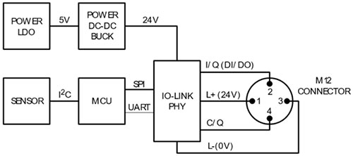
Figure 2: Building blocks of an IO-Link sensor
Analog Devices’ long and committed history with IO-Link technology has resulted in the development of multiple generations of transceivers, on both the IO-Link master and device side, that focus on low power dissipation, small solution size, and robust communications.
ADI has a proven track record of long-term dedication and commitment to the industrial market, and to its customers, by having the industry’s most complete IO-Link and binary sensor portfolios. These include the MAX14828, MAX14827A, MAX22513, MAX22514, and MAX22515 device transceivers.
The MAX14828 single-channel transceiver, and the MAX14827A dual-channel transceiver, dissipate a remarkably low 70mW when driving a 100mA load - achieving more than 80% lower power dissipation than the closest competitive device. The MAX22513 and MAX22514, the latest generation IO-Link transceivers in the ADI portfolio, feature an internal high-efficiency DC-DC buck regulator, low on-resistance drivers (C/Q and DO/DI), selectable driver current limits, and overcurrent protection to further reduce power dissipation for small sensor applications.
Most IO-Link transceivers from ADI are currently available in compact TQFN and WLP packages. The MAX22513, for example, is offered in a WLP package and reduces the solution footprint by up to 50% compared to competitor parts. Additionally, with higher absolute maximum ratings and integrated surge protection, external protection components can be smaller.
IO-Link master design Objectives
When designing an IO-Link master solution, there are common system design questions that must be considered including the number of IO-Link ports, whether ports should be Class A or Class B, what miswiring cases should be accommodated for overvoltage conditions and/or reverse polarity, whether the PCB design be modular and able to accommodate different port counts, how much current the L+ supply should provide, the basic form-factor, and EMC compliance.
One example of an IO-Link master is the MAXREFDES145# eight-port IO-Link master reference design (Figure 3). The design team chose to create an 8-port master due to the popularity of the configuration. The MAXREFDES145# utilizes the MAX14819 dual-channel IO-Link master transceiver and an Arm Cortex-M4 microcontroller. The reference design fits on a single 5in. x 3in. (127mm x 76mm). PCB. ADI partnered with TEConcept to supply IO-Link-compliant software stack. The MAXREFDES145# includes a TVS diode at each of the IO-Link ports and is tested to IEC 610004-2 and IEC 610004-5 for transient immunity to ESD and surge immunity.

Figure 3: MAXREFDES145# 8-Port IO-Link master reference design
IO-Link solutions
To demonstrate transceiver performance, and provide quick and easy evaluation and prototyping for its customers, ADI has a comprehensive collection of IO-Link master and sensor/device reference designs available.
The MAXREFDES145#, discussed above, is an eight channel IO-Link master reference design. This reference design meets the requirements for a standard IO-Link master (including the ability to communicate at all of the data rates, as well as meeting EMC requirements). Similar to the MAXREFDE145#, the MAXREFDES165# is a four channel IO-Link master using the MAX14819.
ADI IO-Link reference designs include circuits ranging from simple sensor measurements (for example, temperature, optical, and distance), to more complex devices including a digital input hub and a solenoid actuator. Table 1 shows a complete list of available IO-Link reference designs.
IO-Link reference designs
| REFERENCE DESIGN | IO-LINK TRANSCEIVER | SENSOR/IO ICs | DESCRIPTION |
|---|---|---|---|
| IO-LINK DEVICE | |||
| MAXREFDES37 | MAX14821 | MAX14821 | IO-Link quad servo driver (TMG) |
| MAXREFDES42 | MAX14821 | MAX31865 | IO-Link RTD temp sensor (IQ2) |
| MAXREFDES163 | MAX14839 | MAX14839 | Binary industrial magnetic sensor |
| MAXREFDES164 | MAX14828 | MAX31875 | IO-Link local temp sensor (TMG and TEConcept) |
| MAXREFDES171 | MAX22513 | MAX22513 | IO-Link distance snsor (TMG) |
| MAXREFDES173 | MAX14827A | MAX31875 | IO-Link local temp sensor (IQ2) |
| MAXREFDES174 | MAX22513 | MAX22513 | IO-Link distance sensor (IQ2) |
| MAXREFDES176 | MAX22515 | MAX22190, MAX22192 | 16-Channel Digital Input Hub (TMG) |
| MAXREFDES177 | MAX22515 | MAX22000 | Universal Analog IO (TMG) |
| MAXREFDES278 | MAX22514 | MAX22200 | 8-Channel Solenoid Actuator (TMG) |
| IO-LINK MASTER | |||
| MAXREFDES145 | MAX14819 | MAX14819 | 8-Port IO-Link master (TE Concept) |
| MAXREFDES165 | MAX14819 | MAX14819 | 4-Port IO-Link master (TMG) |
Conclusion
IO-Link is a powerful technology that plays an increasingly pivotal role in industrial automation. As a smart technology, IO-Link will not only save manufacturers billions of dollars every year but will also expand new markets for more customization of products. If you are involved in any form of industrial automation, integrate IO-Link technology into your products and watch as it continues to unleash the true power of Industry 4.0 and changes the way we think of manufacturing.
Click here to learn more about Maxim Smart Industrial Automation Solutions


